Nail Your First Flip-Flop!
A flip-flop is a kind of circuit that changes back and forth between two states (on and off) at certain intervals. It flips into one state, then flops to another, and so on. With these two states, a flip-flop serves as the most basic binary storage: 0 and 1, "off" and "on." As you can imagine, this makes the flip-flop an important circuit to understand!
This circuit is pretty simple. All you'll need is:
- 4 x 1K Resistors
- 2 x 100K Trim Potentiometers (A.K.A., Trim Pots)
- 2 x 10uF 25v Electrolytic Capacitors
- 2 x N2222A Transistors
- 2 x Blue LEDs
- 1 x 9V Battery Connector
- 1 x BJT Flip Flop PCB
To build this, you'll want to have on hand:
- Your Trusty Soldering Iron and Solder
- A PCB Holder or Helping Hands
- Wire Cutters
- Wire Strippers
- A 5v-12v Power Source
- Heat Shrink Tubing
- Propane Torch

This build is going to be pretty easy, but it will require some soldering in tight spaces. As long as you keep your solder joints separate and orient your components in the correct direction or polarity, you'll do fine.
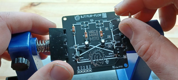
Let the Soldering Commence
To begin, place your NPN Transistors through their designated spot on the PCB. If you're using our custom HackMakeMod board, you can easily tell where they go by the round and flat spot with three through-holes. The shape of the transistor matches the shapes you'll see on the PCB.

Before you solder, it can be helpful to bend the legs underneath so they don't move while you're working.

Now that the transistors are secured and in the right orientation, solder them at their legs.

Once soldered into position, take wire cutters or flush cutters and cut off the legs on the bottom of the PCB. You'll need the room underneath for the other components and their legs.

Next, you'll need to insert your capacitors. Take note of two things: A new capacitor always has a shorter leg on the negative side, and there's typically a white strip with a dash through it, signifying the negative side.

Insert the capacitors into their through-holes with the correct orientation, negative to negative and positive to positive.

Because of how flush the capacitors sit on the board, I like to bend the legs underneath and solder them from below.

After soldering, flush cut these legs. Now we can place our resistors! Bend the legs to create shoulders close to the resistor itself and solder them from the top. You can also bend these below, but it's not entirely necessary. Snip off the legs below to make room for the next component.
Next, we're going to be soldering on our LEDs. Much like the capacitors, you have to solder them in the right orientation. You can tell find the negative side of an LED by its shorter leg, and this longer blade in the LED itself. You can also see a flat spot on the bottom of the LED body. Take a close look!

Place the LEDs in the right orientation, bend the legs outward, and solder them from below.

Last component! Finally, we have pièce de résistance. At the top of the Flip-Flop, we can add our Trimmer Potentiometers, or Trim Pots for short. These are like any other potentiometer, but they can be adjusted by screwdriver.

Match up the legs of the trim pots, bend them outward, and solder them from underneath again. Flush cut those legs off, and we're ready to add power.

We need more power!
Take the exposed ends of your 9 volt battery connector and tin the tips of these wires.

To make life a little easier, you can add a little solder to the GND (Ground) and VCC (Power) through-holes. Then, solder your red wire to the VCC through-hole and your black wire to the GND through-hole.

Then, connect your 9 volt battery, and you should have blinking LEDs!

You can play around with the frequency of the blinking by turning to the left or right on either trim pot. If a light becomes always turned on, its probably just moving faster than the human eye can perceive!

Thanks for joining us on this build! If you had fun and want to share your Flip-Flop, share it on Instagram and tag us with #HackMakeMod!
![Space Drop Handheld Game [Solder Kit]](http://hackmakemod.com/cdn/shop/articles/C0012.00_04_21_15.Still031.jpg?v=1773510848&width=533)